
SBX Assembly Instructions
Installing your N-Possible SBX couplers is easy using the following instructions.

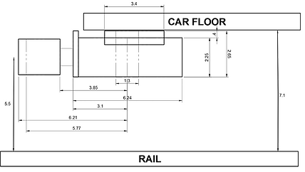
SBX General Arrangement Diagram
Step by Step
Step 1: Plan and Prepare
Make sure you have all of the required parts and plan your installation.
For each coupler you should have a ScaleBox Hat, ScaleBox Top, ScaleBox Bottom, Coupler Knuckle Shank, Coupler Thumb Shank, Coupler Spring and Decorative Airline.
Gather the tools you will need for the installation:
-
Fine grit diamond small file (nail file or emery board also works well)
-
Wooden Toothpick
-
Hobby Knife
-
Soft Pencil for lubrication (i.e. 6B, although standard HB pencil also works)
-
.3MM drill bit for airline install (Tungsten carbide 1/8” shank type recommended, available on Amazon)
-
“Canopy Glue” for airline install
-
00-90 Tap and screws if target model doesn’t have existing body mounting
Perform any modifications that will be needed to the car or coupler box to properly situation the coupler at the right height and with enough space to function.
Coupler height and alignment is critical. Height can be adjusted by shimming or removing material from the box. The “ScaleBox Hat” included in the kit makes the entire assembly mimic a Micro-Trains “1015 Style” coupler assembly.

Ensure there is sufficient space behind the coupler pocket for the N-Possible spring to fit.
Ensure there is adequate horizontal space for the coupler swing. Depending on the radius of curves on your layout and the car length, you may or may not need to account for more or less coupler swing. If you need more swing, you might need to remove material from the box sides to allow for more space for the spring mounts to swing at the back of the coupler pocket.

Step 2: Prepare and Assemble the Coupler Spring and Shanks
Lightly pass over the top of the knuckle shank and the bottom of the retainer shank pivot ring with a fine grit diamond file to remove any burrs.
Lubricate the knuckle shank around the pivot, the retainer ring and the knuckle face and retainer face with a soft (i.e. 6B) pencil.
Slide one end of the coupler spring over the “nub” at the back end of the Coupler Knuckle Shank. There is a slight boss on the end of the nub that should retain the spring.
Slide the other end of the coupler spring over the similar nub on the end of the Coupler Thumb Shank. It also has a slight boss to retain the spring.
The two shanks should now be joined by the spring.

Step 3: Install the Coupler in the Box
The ScaleBox Hat sizes the ScaleBox to match the width and height of “1015” style coupler box. If necessary for your installation, attach the ScaleBox Hat to the ScaleBox Top.
The hat has a mounting pin that fits into a hole on the back of the box top. Place the hat upside down on a hard surface, and then press the box top onto the matching mounting pin.

Install the coupler shank assembly in the ScaleBox. Using a toothpick or other suitable tool, place the box bottom screw hole over the end. Then place the coupler assembly over the pivot post, paying particular attention to ensuring the spring splitter is precisely in the middle of the spring.
Lift the coupler assembly to recenter the spring the splitter as necessary.

Once you are satisfied that the coupler is precisely centered, place the box top (with the hat attached if appropriate) on top of the bottom.
The box top has a friction fit but should not take much force to mate to the bottom. Make sure that the top and bottom are perfectly aligned, as the top interfaces with details on the bottom.

With the coupler box now assembled, verify coupler operation while the box assembly is still on the toothpick. Verify that the coupler is still precisely centered and not binding.
If it’s not operating correctly, gently lift up on the box top to remove it, and re-center the spring on the splitter. If you have binding, make sure there is no debris or support flash binding the coupler.
Step 4: Install the ScaleBox on the model
Mount the coupler to the model. The mounting hole is designed to pass a 00-90 screw (not supplied) with a tight fit. Depending on the installation, you can also reliably glue the box using rubberized CA (Bob smith industries IC 2000). Be very careful if gluing the box not to get glue on any of the moving parts.
When screwing the box onto the model, make sure that the coupler is not binding. ANY binding will potentially cause less reliability, so it’s very important that you ensure that your couplers are not binding, even in the slightest.
If you encounter binding you can first attempt to slightly overtighten the mounting screw, exercise the coupler back and forth in the restricted state, and then loosen things until the coupler snaps back to center.
Signs of binding include a lazy return to center, or not quite but almost returning to center, or binding at the extremes of motion in the box.
Step 5: Install the Airline
This optional step brings even more realism to your models.
Clear out the airline mounting hole with a .3 mm drill bit. Holding the airline with tweezers, add a touch of canopy glue to the end of the airline and slide it into the mounting hole.
Its highly recommended to mount the airline AFTER installing the coupler box on the car.